CAN – ISO 11898, Raw CAN and CANopen
CAN (Controller Area Network) is a powerful serial bus system for a fast data exchange between electronic control units (ECUs). It has a multi-master functionality so that all CAN nodes send data and different CAN nodes can poll the bus simultaneously. It was developed by Robert Bosch GmbH in 1983, initially for automotive technology. In addition to passenger cars and commercial vehicles, CAN networks are increasingly used in ships, trains and airplanes as well as in automation technology and mechanical engineering. Today almost all microcontrollers are equipped with a CAN interface.
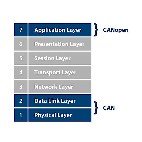
The Data Link Layer – a data backup and physical layer – is defined in the CAN specification which describes the frame structure. Aside the transmitted data are described via CAL (CAN Application Layer). So CAL is a general description language for CAN networks which provides a number of communication services. The serial bus system with the real-time ability is standardized in the international norm ISO 11898 and contains the lowest two layers of the ISO/OSI Layer model. The CAN protocol was standardized in 1993 and is described in the ISO 11898-1 standard.
Application
CAN networks are used as a communication system for microcontrollers in the embedded area and as an open communication system for intelligent devices such as IO modules. The serial bus system is used both in vehicle electronics and in the automation of machines. CAN is characterized by low costs, possible function in various electronic environments, high-precision real-time capability and simple use.
7 Layers of the OSI Model
The OSI model is described by the CAN protocol and includes the data communications and physical layers. The ISO standard defines a standard that includes the CAN specification and parts of the physical layers: The physical signal with bit encoding and decoding (Non-Return to Zero, NRZ) and the bit timing and bit synchronization.

1. Physical Layer: Transmission and reception of raw bit streams over a physical medium
2. Data Link Layer: Reliable transmission of data frames between two nodes connected by a physical layer
3. Network Layer: Structuring and managing a multi-node network, including addressing, routing and traffic control
4. Transport Layer: Reliable transmission of data segments between points on a network, including segmentation, acknowledgement and multiplexing
5. Session Layer: Managing communication sessions, i. e. continuous exchange of information in the form of multiple back-and-forth transmissions between two nodes
6. Presentation Layer: Translation of data between a networking service and an application; including character encoding, data compression and encryption/decryption
7. Application Layer: High-level APIs, including resource sharing, remote file access, directory services and virtual terminals
RAW CAN
RAW CAN refers to the pure CAN protocol, which works on the CAN bus without any additional communication protocol. The CAN protocol is internationally defined according to the ISO 11898-1 standard and guarantees in ISO 16845 the interchangeability of CAN chips in ISO 16845.
Function
CAN is based on a communication mechanism that sends a message to all users.
The transmission of the protocol happens controlled by messages.
CANopen
CANopen is a CAN-based protocol for higher layers which was developed by Bosch as embedded network with flexible configuration stability and handed over to the CAN in Automation (CiA) association in 1995. CANopen was originally designed specifically for motion-orientated machine control networks, but today it is also used in many areas of medicine, commercial vehicles, marine electronics or building automation.
Function
CANopen is a networking concept based on the serial bus system CAN and the application layer CAL. In contrast to CAL, CAN defines which data is to be transmitted with which services and what the data on the respective device classes means. Only a subset of the communication services offered by CAL is used for this purpose. This reduces the required computing power and memory capacity. The CANopen specifications include the application layer, the CANopen communication profile (CiA DS 301) based on CAL protocol, and a framework for programmable machines (CiA 302).
The application layer and the CAN-based profiles are implemented in the software. CANopen network systems can be easily integrated using standardized profiles such as machine, interface and application profiles. CANopen simplifies working with CAN specific details such as bit timing and implementation-specific functions. So it provides standardised communication object for real-time data (Process Data Objects – PDOs), configuration data (Service Data Objects – SDOs), special functions such as time stamps or network management data such as boot-up-message, NMT message or error control.
CANopen-Protocol
The CANopen application layer and the CANopen communication profile support direct access to device parameters and the transmission of time critical process data. The CANopen network management helps with the project design, system integration and diagnostics. Thus, different communication services and protocols can be queried in each decentrally controlled application. CANopen defines all services and protocols as well as the neccessary communication objects. The entire functional scope of a machine is described by communication objects in the object index, which acts as a link between the communication interface and the application program.
CANopen Application
CANopen is applied in control systems in the automation beside the use in small and medium-sized embedded networks.
Function
CAN offers two data communication services: sending a message (data frame transmission) and querying a message (Remote Transmission Request – RTR).
Data transmission is performed by one bit acting either dominant or recessive on the bus lines, depending on its state. A distinction is made between CAN high-speed with a maximum transmission rate of 1 Mbit/s and CAN low speed with 125 Kbit/s. A CAN network is built up in a line structure in which the ends are provided with a terminating resistor of 120 ohms. The “one-wire CAN bus” is also used for bus networking in the car. With the CAN bus, each participant can send data if the bus is free. The CSMA/CA method is used for fast transmission of messages and to avoid collisions.
Each CAN bus participant sends its message to all others. By adding an identification, the other bus participants know what kind of message it is and can then process the data. The filtering of the message is carried out by the bus hardware in the node.
Depending on the bus driver module used, up to 128 CAN bus nodes can be integrated per line. An object identifier indicates the content of a message. This enables the recipients to decide whether a message is relevant to them or not. In addition, the CAN message is positioned with the object identifier. The specification defines 11-bit identifiers and 29-bit identifiers. This means that a bus station can be both a receiver and a sender of messages with any number of identifiers.
